ANY-maze Help > I/O devices supported by ANY-maze > The ANY-maze interface device family > The ANY-maze Digital interface > The ANY-maze Digital interface photobeam ports
The ANY-maze Digital interface photobeam ports
![]()
Contents
This topic contains full details about ANY-maze Digital interface photobeam ports and covers:
| • | An introduction to the photobeam ports |
| • | Configuring a photobeam port |
| • | Connecting to a photobeam port |
| • | Testing a photobeam port |
| • | Photobeam port specification |
An introduction to the photobeam ports
The ANY-maze Digital interface photobeam ports allow ANY-maze to detect breaks of a photobeam. Up to six photobeams can be connected to a single ANY-maze Digital interface (each beam uses two digital ports).
The ANY-maze Digital interface includes some intelligent features which eliminate common problems with photobeams.
| • | The interface 'polls' the photobeams connected to it one at a time. This means that each emitter is switched on, the detector is read and the emitter is then switched off. This process is repeated for each connected beam. The advantage of this approach is that it eliminates cross-beam interference, where the light from the emitter of one beam interferes with another beam. Under this system each individual beam is read at least 150 times each second. |
| • | Depending on the specific devices used, photobeams can work at long ranges (up to 200cm or beyond). |
| • | Beams are relatively immune to ambient infra-red light. The only problem with high ambient infra-red is that it will decrease the range at which the beams will work. |
| • | The specific characteristics of the LED and photo-transistor used are not too important, as the ANY-maze Digital interface will adapt to the devices (although the range will vary). |
The photobeams consist of two parts: an infrared LED (the emitter), which shines infrared light on an infrared-sensitive photo-transistor (the detector). These connect to an ANY-maze Digital interface photobeam port as shown in figure 1 (counting left to right, looking into the port).
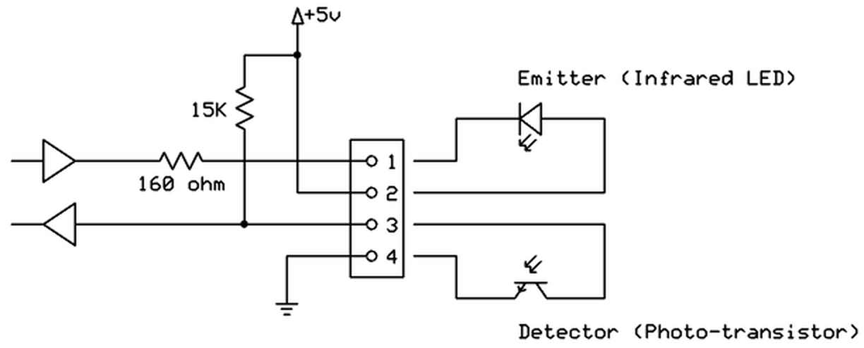
Figure 1. Conceptual internal circuit of an ANY-maze Digital interface photobeam port.
Configuring a photobeam port
To configure a port as a photobeam, you should open the ANY-maze Digital interface configuration window, select the appropriate port and then select Photobeam from the Use this port as a drop down list. This is described in detail here.
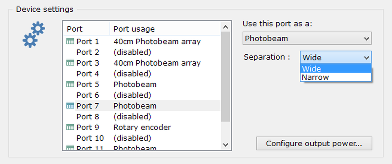
Figure 2. The photobeam port options.
Specifying the beam separation
If the emitter and detector of a photobeam are separated by 10cm or less, then you may find that when the animal interrupts the beam, it is not reported as 'broken'. This is most likely to occur in nose poke holes, where just the animal's nose interrupts the beam - which may not be enough to block all the infrared light from the emitter reaching the detector. To address this, you can specify that the beam separation is 'Narrow'; this causes the port to report a beam break when the amount of infrared light reaching the detector drops, even by a small amount.
If you're not sure what to specify for separation, use 'Wide' (the default); you should only change the setting to 'Narrow' in the circumstance described above.
Connecting a photobeam to a photobeam port
A photobeam uses both of the digital ports on a single ANY-maze Digital interface connector. The specific connections are as follows (counting left to right, looking into the port):
| Pin 1 | Emitter cathode |
| Pin 2 | Emitter anode |
| Pin 3 | Photo-transistor collector |
| Pin 4 | Photo-transistor emitter |
The emitter should be an infrared LED. The cathode should be connected to pin 1 and the anode should be connected to pin 2 (which will be at 5V). The photobeam port includes a 160 ohm current-limiting resistor, so most LEDs can be connected directly to the port (the typical forward voltage of an IR LED is around 1.5V, so the forward current will be (5 - 1.5) / 160 = 22mA). You should try to use an LED with a narrow beam angle as this will improve the range of the photobeam.
The detector should be an infrared photo-transistor (note that the ANY-maze Digital interface photobeam ports do NOT work with photo-diodes). The collector should be connected to pin 3 and the emitter should be connected to pin 4. The photo-transistor you use should be spectrally matched to the LED (i.e. it should be sensitive to the infrared wavelength that the LED emits).
As an alternative to using your own LED and phototransistor, you can use the AMi photobeam, pictured below.
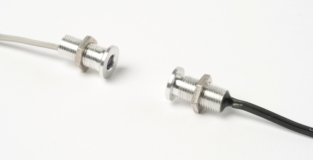
Figure 3. The AMi photobeam. The threaded case makes it simple to mount the beams in a hole.
The AMi photobeams have a grey cable to the emitter and a black cable to the photo-transistor. These connect to the ANY-maze Digital interface connector as follows:
| Pin 1 | Grey cable, silver wire (Emitter cathode) |
| Pin 2 | Grey cable, gold wire (Emitter anode) |
| Pin 3 | Black cable, silver wire (Photo-transistor collector) |
| Pin 4 | Black cable, gold wire (Photo-transistor emitter) |
Testing a photobeam port
After you have connected your photobeam, you will of course want to test it. This is easily done using the I/O page.
| 1. | Open the ANY-maze Digital interface in the list on the left side of the I/O page. |
| 2. | Select the interface's Photobeams, again, in the list on the left side of the page. |
| 3. | The right-hand side of the page will show all the ports that are configured as photobeams. If the beams are aligned then they will be shown with a line between them - as is the case for the beam connected to Port 3-4 in figure 4, below. |
| 4. | Breaking a beam should cause the line between the beams to disappear, as is the case for Port 1-2 in figure 4. |
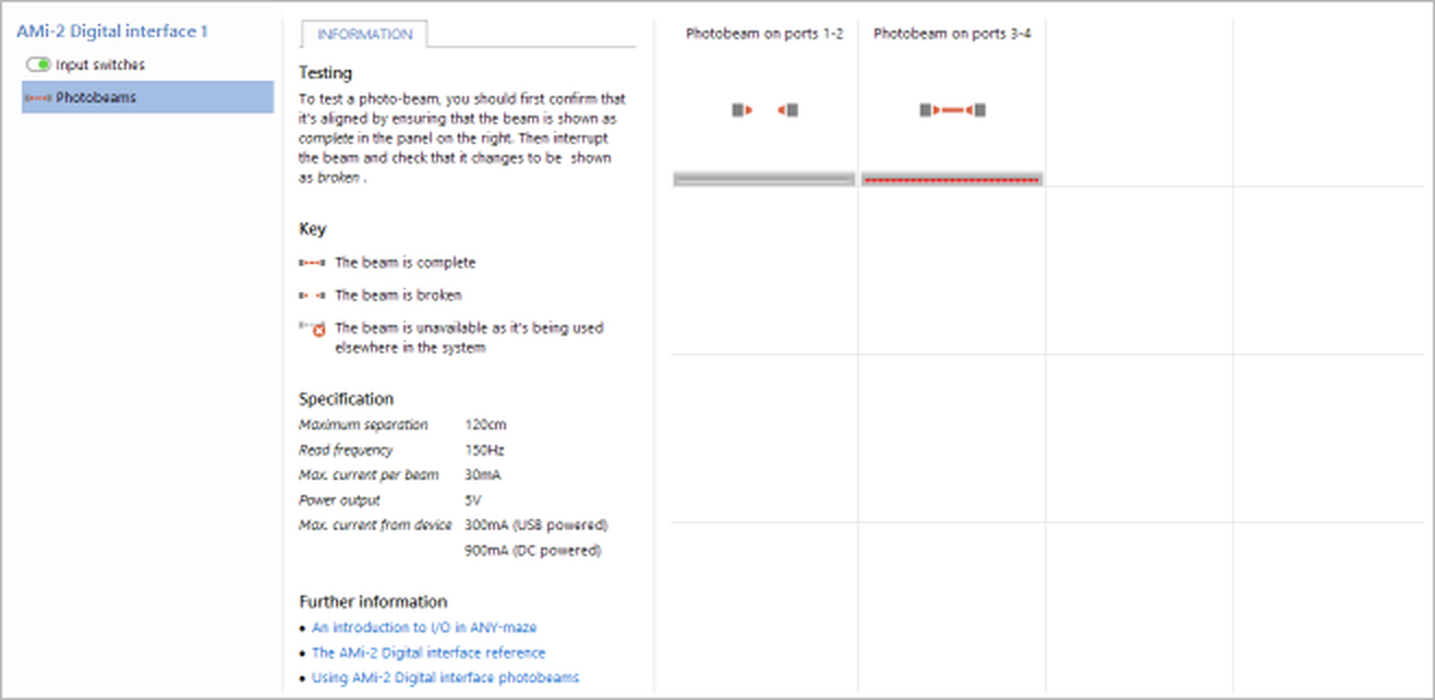
Figure 4. Testing the ANY-maze Digital interface photobeams on the I/O page. Here the photobeam connected to ports 1-2 is broken.
If you find that the beam isn't shown with a line then you should:
| • | Check the wiring - it's easy to wire up an emitter or detector backwards. |
| • | Check the beam is aligned. |
| • | Try reducing the beam separation. First reduce the separation to 1cm - if separation is the problem then the beam should definitely work at this distance - then slowly increase the separation until it stops working, thus you'll find the separation limit. You should use the beam at no more than 80% of its separation limit. |
| • | Check that you're testing the correct port. |
Beam intensity feedback
You'll notice in figure 4 that there's a red bar shown below the photobeam. This shows the beam intensity and can be very useful when aligning the beams. As the beams become aligned you'll find that the bar grows from the left to the right, so when aligning beams your aim is to make the bar go as far to the right as possible. When the beam separation is small, the bar will usually go all the way to the right (as is the case for the photobeam on ports 3-4, in the image), but as the separation increases so the intensity will decrease, so you may find that even when the beam is perfectly aligned the bar only goes halfway - this is normal and provided the overall status of the beam (represented by the graphic above the bar) is shown as not broken then the beam will still work correctly.
Photobeam port specification
| Read frequency | 150Hz |
| Maximum separation | 110cm (for AMi photobeam; other devices will vary) |
| Typical LED current | 22mA |
See also:
| • | An overview of the ANY-maze Digital interface |
| • | Setting up the ANY-maze Digital interface |
| • | Configuring the ANY-maze Digital interface |
| • | Connecting the ANY-maze Digital interface to your equipment and testing it |
| • | Using the ANY-maze Digital interface in tests |
![]()
© Copyright 2003-2026 Stoelting Co. All rights reserved
ANY-maze help topic T1063