ANY-maze Help > I/O devices supported by ANY-maze > The ANY-maze interface device family > The ANY-maze Digital interface > The ANY-maze Digital interface rotary encoder ports
The ANY-maze Digital interface rotary encoder ports
![]()
Contents
This topic contains full details about ANY-maze Digital interface rotary encoder ports and covers:
| • | An introduction to the rotary encoder ports |
| • | Configuring a rotary encoder port |
| • | Connecting to a rotary encoder port |
| • | Testing a rotary encoder port |
| • | Rotary encoder port specification |
An introduction to the rotary encoder ports
The ANY-maze Digital interface rotary encoder ports allow ANY-maze to read incremental rotary encoders (also sometimes called quadrature or quadratic encoders). These devices detect rotations of an axle and output 'pulses' as the axle turns. ANY-maze can use these pulses to determine both how much the axle rotates and in what direction.
The ANY-maze Digital interface will work with incremental encoders that have TTL or open-collector outputs and which require either 5V power, or no power at all.
A rotary encoder outputs two digital signals and therefore uses both the digital inputs on an ANY-maze Digital interface port. This means you can connect up to 6 encoders to a single interface.
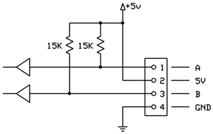
Figure 1. Conceptual internal circuit of an ANY-maze Digital interface rotary encoder port. (The port pins are numbered left to right, looking into the port).
Configuring a rotary encoder port
To configure a port as a rotary encoder, you should open the ANY-maze Digital interface configuration window, select the appropriate port and then select Rotary encoder from the Use this port as a drop down list. This is described in detail here.
When a port is configured as a rotary encoder, some additional options are available in the configuration window - see figure 2, below:
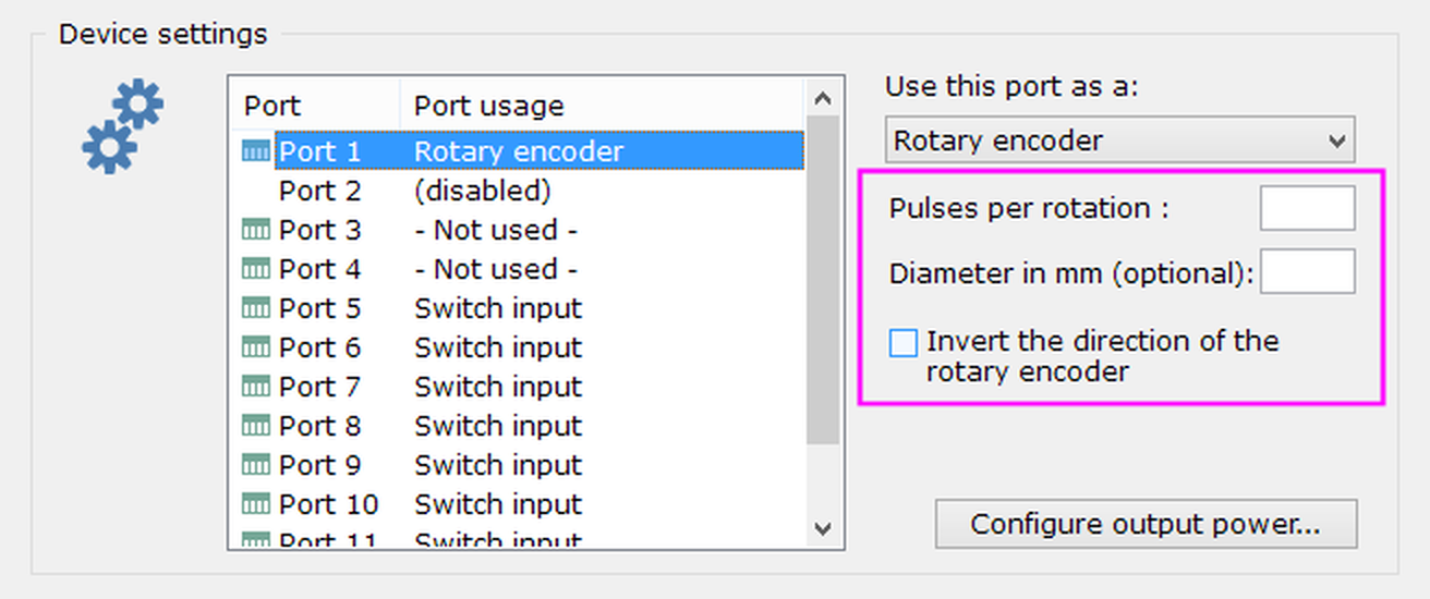
Figure 2. The rotary encoder port options.
Specifying the pulses per rotation
As a rotary encoder turns through 360 degrees it outputs a fixed number of equally spaced pulses, for example, it might output 30 pulses per rotation (PPR), which would mean it would output one pulse for every 12 degrees of rotation. In order for ANY-maze to correctly interpret the pulses, it needs to know the number of pulses per rotation of the encoder connected to the port; this will be detailed in the encoder's technical specification.
Specifying the diameter of the thing that's rotating
The most common use for a rotary encoder is to use it to measure the number of rotations of an animal's running wheel. While knowing that an animal ran, say, 4,381 rotations is useful, you might prefer to see how far (in metres) the animal actually travelled. Clearly this will depend on the diameter of the wheel and if you specify it here then ANY-maze will do the maths for you and report distance as well as number of rotations.
Inverting the direction of rotation
Rotary encoders have two outputs, usually called A and B (there's more on this below). These output digital signals that are out of phase and this is what allows the ANY-maze Digital interface to determine the direction of rotation. However, different encoders work differently and you may find that if you connect A and B in the way described in the next section, then your encoder will report clockwise turns when you turn it counter-clockwise and vice versa. To fix this you can either switch the A and B connections or, more simply, just check the box to invert the direction.
Connecting a rotary encoder to a rotary encoder port
A rotary encoder uses both of the digital ports on a single ANY-maze Digital interface connector. The specific connections are as follows (counting left to right, looking into the port):
| Pin 1 | A |
| Pin 2 | 5V |
| Pin 3 | B |
| Pin 4 | GND |
A and B are the usual names given to the digital signals output by an encoder, but your encoder might call them something different. Whatever they're called, just connect one output to Pin 1 and the other to Pin 3, without worrying about which way round they should go; this might mean that the encoder seems to work backwards (when you turn it clockwise it shows counter-clockwise rotations and vice versa), but if that happens you can either reverse the connections to Pins 1 and 3 or use the option to invert the direction of rotation.
Some encoders include an Index signal. The ANY-maze Digital interface doesn't use this signal and you don't need to connect it.
Some encoders don't require the 5V line, in which case you can just not connect it. Note that you shouldn't try to use an encoder which requires a power voltage other than 5V.
We provide an AMi rotary encoder, pictured below. Further details are available on our website.
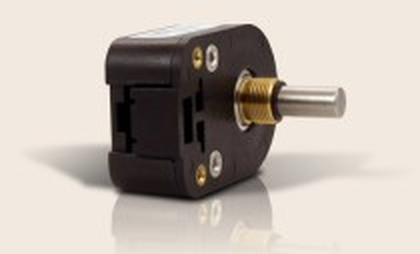
Figure 3. The AMi rotary encoder.
The encoder is supplied with a cable ready to be connected to an ANY-maze Digital interface rotary encoder port. This cable has coloured wires, and connects to the port as follows:
| Pin 1 | Blue wire (A) |
| Pin 2 | Orange wire (5V) |
| Pin 3 | Yellow wire (B) |
| Pin 4 | Brown wire (GND) |
Testing a rotary encoder port
After you have connected your rotary encoder, you will of course want to test it. This is easily done using the I/O page.
| 1. | Open the ANY-maze Digital interface in the list on the left side of the I/O page. |
| 2. | Select the interface's Rotary encoders, again, in the list on the left side of the page. |
| 3. | The right-hand side of the page will show all the ports that are configured as rotary encoders - see figure 4. |
| 4. | Turn the encoder, and you should see the graphic on the screen turn at the same time. |
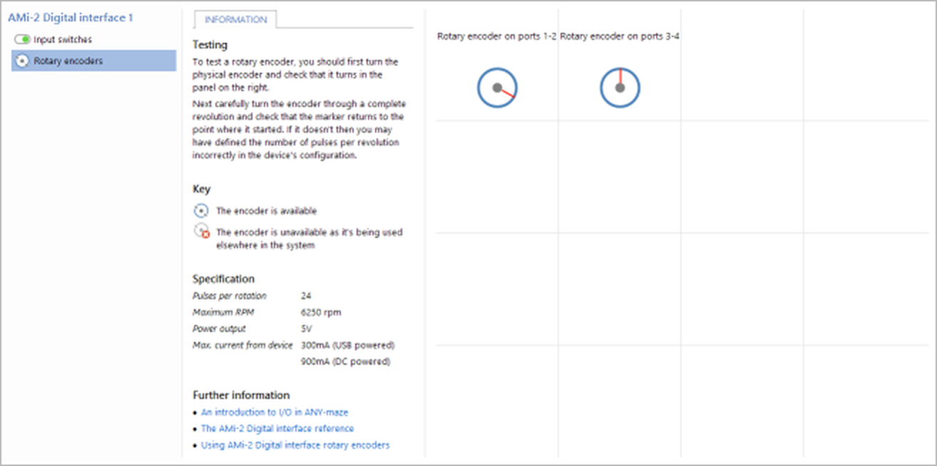
Figure 4. Testing the ANY-maze Digital interface rotary encoders on the I/O page. Here the encoder connected to ports 1-2 has been turned clockwise by about 100°.
If you find that the encoder graphic on the screen doesn't turn, then you should:
| • | Check the wiring |
| • | Check that you're testing the right port |
If you find that the encoder graphic on the screen turns in the opposite direction to the direction that you're actually turning the encoder, then you should either:
| • | Switch the connections to Pins 1 (A) and 3 (B) of the ANY-maze Digital interface rotary encoder port |
OR
| • | Use the configuration option to invert the direction of rotation |
If you find that the encoder graphic on the screen turns more or less than one rotation for each rotation of the physical encoder, then you need to alter the number of pulses per rotation (PPR). The most common issues are for the graphic to turn two complete rotations for one rotation of the encoder, in which case you should double the value you entered for PPR; or for the graphic to turn half a rotation for one rotation of the encoder, in which case you should halve the value you entered for PPR.
And if you get stuck, don't panic - just contact ANY-maze Support who will be happy to help.
Rotary encoder port specification
| Power output | 5V |
| Max power current | 300mA (USB powered), 900mA (DC powered) |
Something else you may wish to know is the maximum number of rotations per minute (RPM) that the encoder will support. This depends on the pulses per rotation (PPR) of the encoder, but ANY-maze will show it under Information > Specification on the I/O page when a rotary encoder port is selected.
See also:
| • | An overview of the ANY-maze Digital interface |
| • | Setting up the ANY-maze Digital interface |
| • | Configuring the ANY-maze Digital interface |
| • | Connecting the ANY-maze Digital interface to your equipment and testing it |
| • | Using the ANY-maze Digital interface in tests |
![]()
© Copyright 2003-2026 Stoelting Co. All rights reserved
ANY-maze help topic T1064