ANY-maze Help > I/O devices supported by ANY-maze > The ANY-maze interface device family > The ANY-maze Digital interface > The ANY-maze Digital interface TTL input ports
The ANY-maze Digital interface TTL input ports
![]()
Contents
This topic contains full details about ANY-maze Digital interface TTL input ports and covers:
| • | An introduction to the TTL input ports |
| • | Configuring a TTL input port |
| • | Connecting to a TTL input port |
| • | Testing a TTL input port |
| • | TTL input port specification |
An introduction to the TTL input ports
The ANY-maze Digital interface TTL input ports allow ANY-maze to read the state of a TTL signal generated by some other device. For example, a vibration monitor might output a TTL signal whenever it detects that an animal is scratching.
The interface device checks a TTL input 10,000 times each second and whenever it changes state it sends a message to ANY-maze.
The 'pin-out' of the ANY-maze Digital interface ports is as follows (counting left to right, looking into the port):
| Pin 1 | Digital port N |
| Pin 2 | GND |
| Pin 3 | Digital port N+1 |
| Pin 4 | GND |
A TTL signal simply connects to a digital port and GND. So it could be connected to pins 1 and 2 or pins 3 and 4.
Internally, ANY-maze Digital interface digital ports are 'pulled-up' to 5V via a 15K resistor and include a 160 ohm series resistor; however in practice the port can be viewed as a direct TTL input.
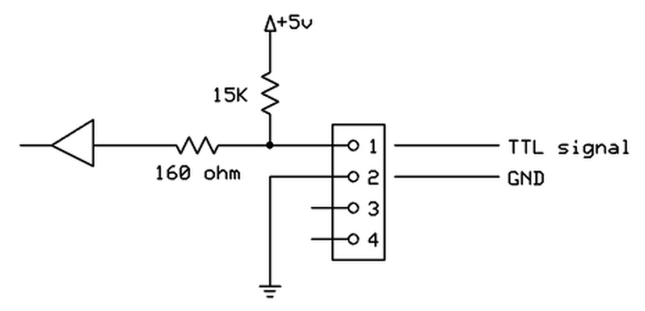
Figure 1. Conceptual internal circuit of an ANY-maze Digital interface TTL input port. The same circuit applies to pins 3 and 4 as well.
Configuring a TTL input port
To configure a port as a TTL input, you should open the ANY-maze Digital interface configuration window, select the appropriate port and then select TTL input from the Use this port as a drop down list. This is described in detail here.
When a port is configured as a TTL input, some additional options are available in the configuration window - see figure 2, below:
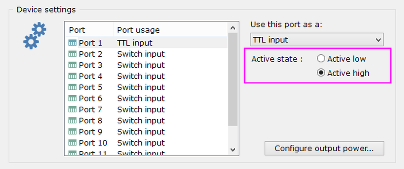
Figure 2. The TTL input port options.
Changing the port's active state
As you'd probably expect, the ANY-maze Digital interface will consider that a TTL input is active when it is HIGH and inactive when it is LOW. This is usually correct, but you may find that the equipment that is creating the TTL signal is 'active low', that's to say when it is active it outputs a LOW and when inactive a HIGH. If this is the case then you can use the port's Active state options to change the input's configuration accordingly.
Connecting devices to a TTL input port
The 'pin-out' of the ANY-maze Digital interface ports is as follows (counting left to right, looking into the port):
| Pin 1 | Digital port N |
| Pin 2 | GND |
| Pin 3 | Digital port N+1 |
| Pin 4 | GND |
You should connect the TTL signal to either pin 1 or 3, and GND to either pin 2 or 4. The two GND pins (2 and 4) are the same, so you can connect to either of them (this is important if you change Pin 2 to be 5V). Note that you MUST connect BOTH the TTL signal line and the GND line from the equipment that is generating the signal.
Testing a TTL input port
After you have connected your equipment to a TTL input port, you will of course want to test it. This is easily done using the I/O page.
| 1. | Open the ANY-maze Digital interface in the list on the left side of the I/O page. |
| 2. | Select the interface's Input switches, again, in the list on the left side of the page. |
| 3. | The right-hand side of the page will show all the ports that are configured as TTL (or switch) inputs; normally they should all be inactive (red). |
| 4. | Do something to cause the connected equipment to activate its TTL output - the relevant port should then be shown as active (green) - see figure 4, below. |
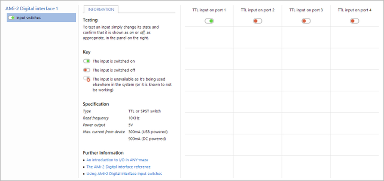
Figure 3. Testing the ANY-maze Digital interface on the I/O page. Here the equipment connected to port 1 is active.
If you find that the port seems to be shown as active (green) when the equipment is inactive and inactive (red) when the equipment is active, then you probably need to change the port's active state.
If you find that the port doesn't register as active (green) when the equipment is active, you should check the wiring and also double check that the port the equipment is connected to is indeed configured as a TTL input and that you're testing the correct port.
TTL input port specification
| Read frequency | 10KHz |
| Power output | 5V (available on Pin 2, if so configured) |
| Max power current | 300mA (USB powered), 900mA (DC powered) |
See also:
| • | An overview of the ANY-maze Digital interface |
| • | Setting up the ANY-maze Digital interface |
| • | Configuring the ANY-maze Digital interface |
| • | Connecting the ANY-maze Digital interface to your equipment and testing it |
| • | Using the ANY-maze Digital interface in tests |
![]()
© Copyright 2003-2026 Stoelting Co. All rights reserved
ANY-maze help topic T1061