ANY-maze Help > The ANY-maze reference > The Protocol page > The elements of a protocol > Apparatus > Apparatus > Setting up a piece of apparatus > Drawing the apparatus map
Drawing the apparatus map

In brief
In order for ANY-maze to understand which parts of a video image constitute your apparatus, you must draw an apparatus map in the Image pane. This map should at least define the border of your apparatus, although you will often want to divide the apparatus into different areas as well.
To draw the map, you should use the various drawing tools (line, circle, rectangle, etc.) which are shown at the top of the Image pane. These work much like drawing tools in other software you might have used.
| • | The structure of an apparatus map |
| • | The drawing tools |
| • | Drawing operations |
| • | Drawing the apparatus border |
| • | Dividing up the apparatus |
The structure of an apparatus map
The apparatus map always defines the borders of your apparatus, and will usually divide the apparatus into different parts as well. The borders are very important, as ANY-maze only looks for an animal inside the borders that you draw, while dividing up the apparatus is optional.
An apparatus map in ANY-maze is made up of various drawing objects, such as lines, circles and rectangles. For example, the map in figure 1 consists of three objects; a circle and two lines. These objects are drawn using the drawing tools.
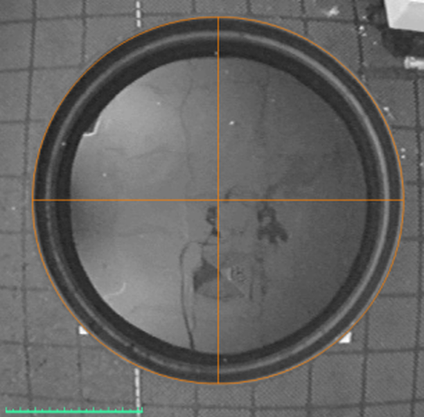
Figure 1. A simple apparatus map for a water-maze, consisting of a circle and two lines.
The drawing tools
The various drawing tools are shown in the ribbon bar when an apparatus element is selected - you select a tool by clicking it.
 | Some of the vertices of drawing objects are slightly magnetic, that's to say that they attract one another - this makes it very easy to neatly join objects together. |
 Select objects Select objects | Use this tool to select objects in a drawing. To use it, simply point at a line of the object you want to select (the mouse pointer will change to a four-headed arrow) and click the left mouse button. Small boxes will be drawn on the object's vertices - as well as allowing you to resize the object, these also indicate that the object is selected. |
 Multiline tool Multiline tool | Draws a multi-line. A multi-line is a series of connected lines. The first line starts where you click the left-hand mouse button, and ends where you release it. The next line starts where the first line ended, and ends where you click next - using this technique you can build up a series of any number of connected lines. To end a multi-line, double click the mouse. Multi-lines are very useful for drawing around apparatus such as a plusmaze. The magnetic vertices of a multi-line are the end points of each line. A multi-line's vertices will also attract each other, making it easy to close a multi-line object - see figure 2. |
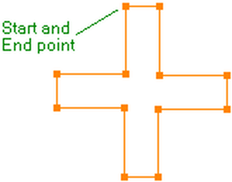
Figure 2. The borders of a plusmaze, drawn with a multi-line. The start and end vertices align perfectly, because they attract each other.
 Rectangle tool Rectangle tool | Draws a rectangle. The top left corner of the rectangle will be where you click the left-hand mouse button, and the bottom left corner will be where you release it. The magnetic vertices of a rectangle are its corners and the centre of each side. |
 Ellipse tool Ellipse tool | Draws an ellipse. The top left 'corner' of the ellipse will be where you click the left-hand mouse button, and the bottom left 'corner' will be where you release it. Obviously an ellipse doesn't actually have any corners, but if you try drawing one you'll see what I mean. The magnetic vertices of an ellipse are its pole points. |
 Line tool Line tool | Draws a single line. The line will start where you click the left-hand mouse button, and will end where you release it. The magnetic vertices of a line are its end points. |
 Grid settings Grid settings | The grid tool is used to add a regularly spaced grid to a map. For full details about grids, see the Apparatus map grids topic. |
 Select all Select all | Causes all the drawing objects to be selected, allowing you to move, copy or delete them all simultaneously. |
 Points attract Points attract | Toggles the magnetic attraction of vertices on and off. Switching this off can be helpful when you want two vertices to be close together but NOT touching. |
Drawing operations
Adding objects
To add an object to an apparatus map, you should first select an appropriate drawing tool - see above. Next, click and hold down the left mouse button somewhere in the video picture. Now with the button still held down, move the mouse - the object will appear and will get bigger and smaller as you move the mouse around. When you're happy with the object's size, release the mouse button.
Resizing and moving objects
Once an object has been included in the apparatus map, it's very easy to move and/or resize it. To do this, first check that the  Select objects button is selected and then move the mouse over one of the object's lines - the mouse pointer will change to a four-headed arrow. If you now click the left-hand button, the object will become selected - some little boxes will appear around it. You can then drag the boxes to resize the object, or drag any of its lines to move it.
Deleting objects
Deleting an object is very simple. First select it (i.e. click on one of its lines) and then press the 'Delete' key on the keyboard.
Joining objects
The vertices of ANY-maze drawing objects are slightly magnetic, in other words they attract each other. If you move the vertices of two objects close together they'll stick to each other just like moving two magnets close together. This is very useful as it makes it easy to create neat drawings in which objects join up nicely; and this isn't just an aesthetic issue - gaps in drawings can mean that areas you intended to be separate are actually treated as one.
Copying and pasting objects
To copy an object, just select it (i.e. click on one of its lines) and then click the  Copy button. (Alternatively, you can use Ctrl+C on the keyboard or you can right click and select Copy from the menu which appears.)
Having copied a drawing object you can paste it into the same apparatus map, or into a different one, simply by clicking the  Paste button. (Alternatively you can use Ctrl+V or you can select Paste from the right click menu.)
It can be very useful to copy all the objects in a drawing, as you can then paste the complete drawing into another piece of apparatus. (Remember, you can select all the objects by clicking the  Select all button).
 | Another way to copy an object is to click and drag while holding down the Ctrl key - you'll end up dragging a duplicate of the object you clicked on. |
Drawing the border
You must draw a border around your apparatus in order for ANY-maze to work. The border doesn't actually have to go exactly round the apparatus; nevertheless you shouldn't just draw a big box with the apparatus somewhere inside. Ideally you should draw a border that neatly encloses the apparatus - see figure 1.
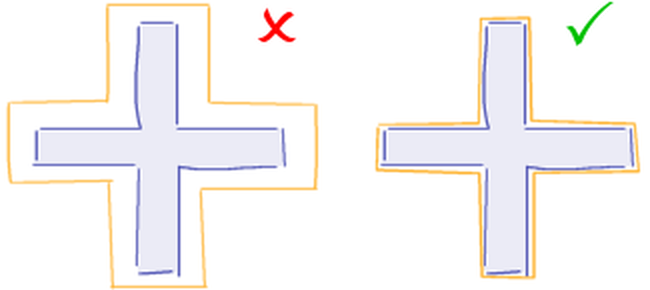
Figure 1. In the first picture the border is too loose, whereas in the second it's just right.
For a technical reason, it's better to draw the apparatus border using either a rectangle, an ellipse or a multi-line; in other words, avoid using lots of individual lines. That said, if you do use lots of lines ANY-maze will still work correctly.
Dividing up the apparatus
After you've drawn the border of the apparatus, you will probably want to divide it into different areas. For example, in a plusmaze you'll probably want to divide off the arms and possibly the ends of the arms too. Without this type of division, ANY-maze won't be able to report on activity in different parts of the apparatus; it will just treat the whole apparatus as a single area - see figure 2.
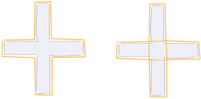
Figure 2. The apparatus map on the left doesn't include any internal divisions. ANY-maze will only be able to report on activity in the apparatus as a whole. The map on the right however, has the arms divided off. Now ANY-maze will be able to report on activity in the open and closed arms, as well as in the apparatus as a whole.
It's important to understand two things. Firstly, that the areas you create will be the lowest level at which ANY-maze will be able to report information, and secondly that it's very easy to group areas together. For example, if you don't divide off the ends of the arms in a plusmaze, then ANY-maze won't be able to report on activity for the ends of the arms as distinct to the rest of the arm. However, if you do divide off the ends of the arms, then you can easily group together the two parts of the arm to get information for the arm as a whole - see figure 3.
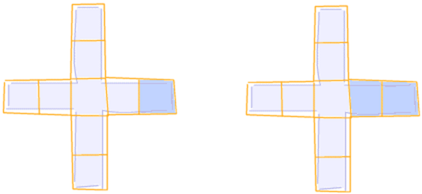
Figure 3. With this apparatus map, ANY-maze can report on activity in any individual area, such as the end of an arm (left), or any combination of areas, such as an entire arm (right).
Of course, you might be tempted to go crazy and divide your apparatus into tiny areas and then group them together so as to guard against the possibility that at some point you might want to know something about an area that isn't defined in your map. Don't worry! You don't need to do this, because you can always edit the apparatus map, before, during or even after an experiment - so if you realise you want information about an area which isn't divided off in your map, you can simply edit the map so it is.
In some cases, you may want to divide your apparatus into equal-sized areas, for example into 10cm squares. Of course, you could do this using lots of lines, but making the squares exactly 10cm might be challenging and drawing all the lines would be a little tedious! Fortunately, ANY-maze includes an ability to draw grids which make this type of operation very simple - see the Grid Settings topic for details.
There are a few other things to note when dividing up your apparatus.
| • | If a dividing line doesn't quite close an area, then ANY-maze won't consider the area as being a separate part of the apparatus - see figure 4. Fortunately, the 'magnetic attraction' between vertices often helps to eliminate this problem, as do grids - which will always fully divide areas. However, if neither of these help in your apparatus, then you can simply draw lines which are a little too long - as is the case in figure 4. |
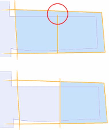
Figure 4. In the first map, the dividing line doesn't quite close off the end of the arm so ANY-maze considers all of the area in blue to be a single area. In the second map, the line fully closes off the end of the arm so it's now considered to be a separate area.
| • | There's a maximum limit of 250 different areas in a single apparatus. This sounds like a lot, but when using grids it's not too difficult to reach it - for example, a 1.5m x 1.5m open field with a 10cm grid would contain 225 areas. Nevertheless, it's usually easy to reduce the number of areas in these circumstances. |
| • | You may be tempted to use a grid in your apparatus because you used one when you were scoring behaviours manually. However, you should carefully consider whether the grid is actually required. For example, you might have painted a grid onto an open field so you could use 'line crossings' as a way to measure locomotor activity. As ANY-maze can report locomotor activity by measuring the distance an animal travelled during a test, then the grid (at least for this purpose) is redundant. Of course, for the sake of consistency you may want to continue using grid line crossings to measure locomotor activity, in which case you can simply include the grid and ANY-maze will measure the crossings for you. |
 | When using ANY-maze in Freezing detection only mode, you only actually need to draw the border of the apparatus. However, you can still draw divisions within your apparatus map if you want to; they will just be ignored by the system. |
See also:
| • | Grid Settings |

© Copyright 2003-2026 Stoelting Co. All rights reserved
ANY-maze help topic T0123