ANY-maze Help > I/O devices supported by ANY-maze > The ANY-maze interface device family > The ANY-maze Digital interface > The ANY-maze Digital interface TTL output ports
The ANY-maze Digital interface TTL output ports
![]()
Contents
This topic contains full details about ANY-maze Digital interface TTL output ports and covers:
| • | An introduction to the TTL output ports |
| • | Configuring a TTL output port |
| • | Connecting to a TTL output port |
| • | Testing a TTL output port |
| • | TTL output port specification |
An introduction to the TTL output ports
The ANY-maze Digital interface TTL output ports allow ANY-maze to control equipment that has a TTL input. For example, this might be a shocker with a 'TTL activate' input, or a pellet dispenser with a 'TTL dispense' input. ANY-maze Digital interface TTL output ports can also be used to directly drive an LED and can be used to synchronise ANY-maze with other systems that have TTL inputs.
The 'pin-out' of the ANY-maze Digital interface ports is as follows (counting left to right, looking into the port):
| Pin 1 | Digital port N |
| Pin 2 | GND |
| Pin 3 | Digital port N+1 |
| Pin 4 | GND |
A TTL output simply connects to a digital port and GND. So it could be connected to pins 1 and 2 or pins 3 and 4.
Internally, ANY-maze Digital interface digital ports are 'pulled-up' to 5V via a 15K resistor and include a 160 ohm series resistor - these resistors have no effect when connecting directly to equipment with a TTL input but the 160 ohm resistor is critical when using a TTL output port to drive an LED.
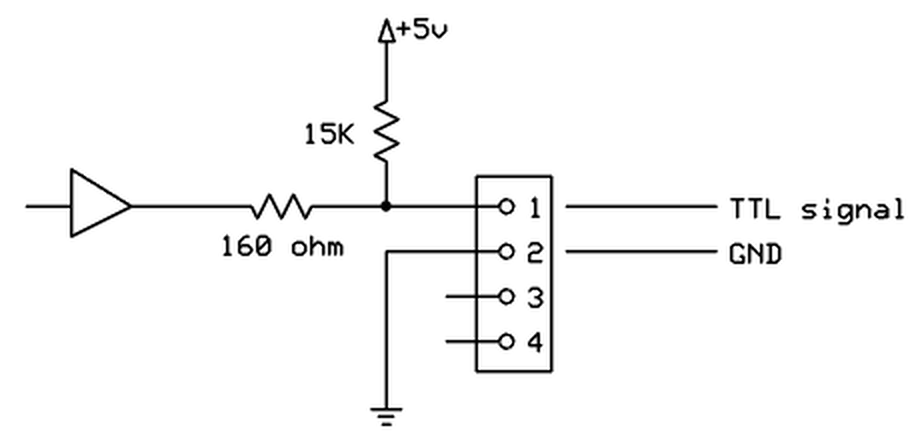
Figure 1. Conceptual internal circuit of an ANY-maze Digital interface TTL output port. The same circuit applies to pins 3 and 4 as well.
Configuring a TTL output port
To configure a port as a TTL output, you should open the ANY-maze Digital interface configuration window, select the appropriate port and then select TTL output from the Use this port as a drop down list. This is described in detail here.
When a port is configured as a TTL output, some additional options are available in the configuration window - see figure 2, below:
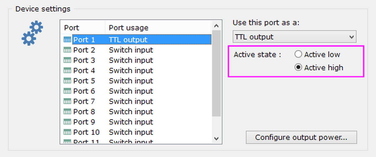
Figure 2. The TTL output port options.
Changing the port's active state
As you'd probably expect, the ANY-maze Digital interface will output a TTL HIGH signal when it is active and a LOW signal when it is inactive. This is usually correct, but you may find that the equipment that you're connecting to has 'active low' inputs, that's to say that to activate it one needs to output a LOW signal. In this case, you can use the port's Active state options to change the output's configuration accordingly.
Connecting devices to a TTL output port
The 'pin-out' of the ANY-maze Digital interface ports is as follows (counting left to right, looking into the port):
| Pin 1 | Digital port N |
| Pin 2 | GND |
| Pin 3 | Digital port N+1 |
| Pin 4 | GND |
Connecting to equipment that has a TTL input
You should connect the TTL signal to either pin 1 or 3, and GND to either pin 2 or 4. The two GND pins (2 and 4) are the same, so you can connect to either of them (this is important if you change Pin 2 to be 5V). Note that you MUST connect BOTH the TTL signal line and the GND line to the equipment that you want to control.
Connecting an LED
To connect to an LED you should connect the LED's anode (usually the longer leg of the LED) to Pin 1 or 3 and the LED's cathode (usually the shorter leg of the LED) to pin 2 or 4. If you connect the LED backwards it won't work, but it won't be damaged either, so if you're not sure which is the anode and which the cathode just try connecting it both ways.
Usually LEDs require what's called a current-limiting resistor - as the name implies this limits the current that will flow through the LED to the level the LED is designed for. The ANY-maze Digital interface TTL output ports include a built-in 160 ohm resistor, so you usually won't need to add a current-limiting resistor yourself. However, it's still a good idea to check the current won't exceed the LED's maximum, which you can do by using the following formula:
Current (amps) = (5 - LED forward voltage) / 160
The LED forward voltage can be found in the LED datasheet, but usually it's around 2V for red and orange LEDs and around 3.5V for green and blue. So for red and orange the above formula tells us the current will be around 20mA, and for green and blue around 10mA. Most LEDs are designed to work at a current of around 20mA or less, so red and orange LEDs will be at their ideal current while green and blue will be less, which means they'll be a bit dimmer, but usually still bright enough to make a good cue lamp.
If you apply the above formula and find that the current will exceed the maximum forward current of the LED you want to use, then you should add your own current-limiting resistor to reduce the current. Use this formula to calculate the resistor to use:
Resistor in ohms = ((5 - LED forward voltage) / (Max forward current in amps)) - 160
As an alternative to using your own LED, you can just buy an LED cue light from us. We supply a range of colours in sealed assemblies which mount directly into a drilled hole - check out our web site to learn more.
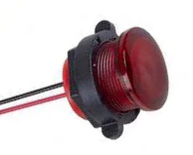
Figure 3. A red AMi cue light. The two wires connect directly to a TTL output port.
Using a TTL output to synchronise with another system
If you are tracking animals in ANY-maze while simultaneously recording data with, for example, an electrophysiology system, then you will probably need some method by which you can align the data from the two systems. This can easily be achieved by having ANY-maze output a TTL signal at the start of the test and recording this signal in the other system. For example, if an electrophysiology system records the TTL signal changing from LOW to HIGH at time 365.178 seconds then deducting this value from the times at which other events are recorded by the system, will tell you when these events occurred in 'ANY-maze time' (in which time zero is the start of the test). In fact there will be a small inaccuracy in these times, because it takes between one and two milliseconds for the TTL output to change after the test begins.
To use an ANY-maze Digital interface TTL output in this way you need to:
| • | Configure a port as a TTL output |
| • | In your protocol, add a new on/off output |
| • | In the on/off output settings, select the option to Activate when the test starts |
| • | Select the TTL output port as the on/off output's Port to use |
Testing a TTL output port
After you have connected your equipment to a TTL output port, you will of course want to test it. This is easily done using the I/O page.
| 1. | Open the ANY-maze Digital interface in the list on the left side of the I/O page. |
| 2. | Select the interface's Output switches, again, in the list on the left side of the page. |
| 3. | The right hand side of the page will show all the ports that are configured as TTL outputs; they will all be shown as inactive (red). |
| 4. | Click on one of the ports to activate it - it will turn green (like Port 1 in figure 4, below) and the output will change to the 'active' TTL signal (which will normally be HIGH). The equipment connected to the output should then activate. |
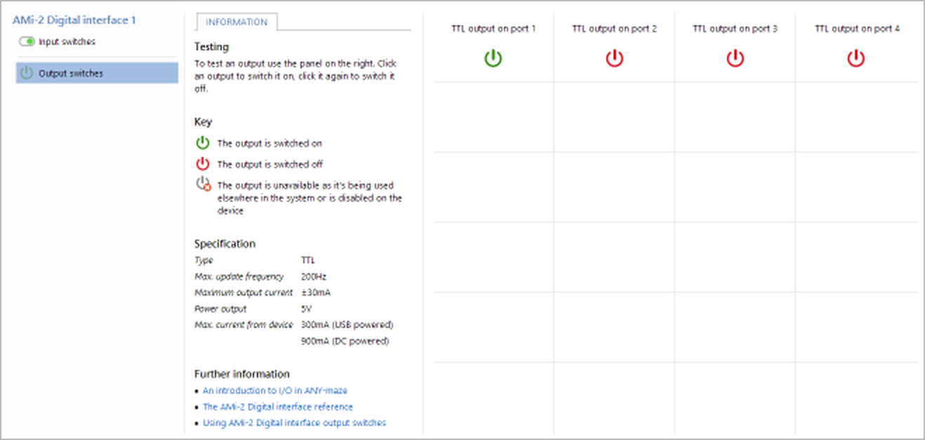
Figure 4. Testing the ANY-maze Digital interface on the I/O page. Here the equipment connected to port 1 has been activated.
If you find that the equipment does not activate when you activate the port then:
| • | Check the wiring |
| • | Check the port you're activating is indeed the port you've connected the equipment to |
| • | Check the port's active state and alter it if necessary. |
If all else fails, then contact ANY-maze Support who'll be happy to help.
TTL output port specification
| Maximum update frequency | 200Hz |
| Maximum output current | ±30mA |
| Output series resistor | 160 ohm |
| Power output | 5V (available on Pin 2, if so configured) |
| Max power current | 300mA (USB powered), 900mA (DC powered) |
See also:
| • | An overview of the ANY-maze Digital interface |
| • | Setting up the ANY-maze Digital interface |
| • | Configuring the ANY-maze Digital interface |
| • | Connecting the ANY-maze Digital interface to your equipment and testing it |
| • | Using the ANY-maze Digital interface in tests |
![]()
© Copyright 2003-2026 Stoelting Co. All rights reserved
ANY-maze help topic T1062