ANY-maze Help > The ANY-maze reference > The I/O page > Making I/O connections > Connecting using generic digital I/O devices > Turning something on and off
Turning something on and off
![]()
| The details given in this topic provide guidance on controlling a device using a generic I/O device such as the Switch and Sense 8/8. Controlling a device using the ANY-maze interface is much simpler - refer to the ANY-maze interface topic for further details. |
Introduction
The purpose of this topic is to describe how to use a generic I/O device to turn some equipment on and off. This might be a lamp, a buzzer, a shocker, etc.
| • | Types of output |
| • | Relay outputs |
| • | TTL outputs |
| • | Open collector outputs |
Types of output
The generic I/O devices supported by ANY-maze have three types of output, TTL level outputs, open collector outputs and relay outputs. Of these relay outputs are far and away the most useful, indeed other than specific situations, TTL and open collector outputs generally can't be used to switch anything on and off.
Relay outputs
As you may know, a relay is simply a mechanical switch that can be activated electronically. Thus your computer can send a signal to the I/O device which can close or open the switch. Most relays in I/O devices are of what's known as Form C relays meaning they have switch inside them, like the one shown in figure 1.
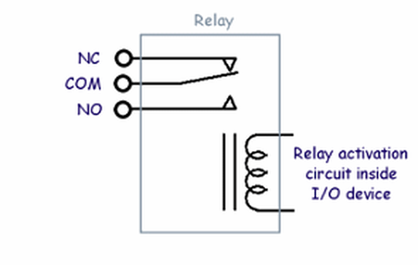
Figure 1. A Form C relay. When the relay is inactive the COM terminal is connected to the NC terminal, when activated the COM terminal is connected to NO.
As can be seen in figure 1, the relay has three terminals COM (common), NC (normally closed) and NO (normally open). When the relay is inactive the COM and NC terminals are connected together, when the relay activates the COM-NC connection is broken and the COM terminal connects to NO. So using a relay as a simple on/off switch is very easy, you just connect to the COM and NO terminals. In fact, in some cases you may wish to connect to COM and NC - that way when the relay is inactive your switch will be on and when the relay activates the switch will turn off.
Although relays are very easy to work with, there are a few things to watch out for:
| • | Relays have a certain voltage rating. So, for example, you can't use a relay with a 120VAC rating, to switch a mains-powered lamp in the UK, where the mains voltage is 240VAC. |
| • | Relays have a certain current rating. This can vary widely depending on the device and you should pay close attention to it. For example, some relays in devices supported by ANY-maze have a current rating of 5 amps, while for others the rating is 0.5 amps. |
| • | The ratings for AC and DC voltages will usually be different, with the ratings for DC voltages being significantly lower than for AC. |
| • | As relays are mechanical switches they usually make a 'click' sound as they open and close. In some situations this may act as a cue to animals in which case you might want to consider using 'solid-state' relays instead. As the name implies, a solid-state relay isn't a mechanical switch, although it can still be viewed as one from the usage point of view. None of the generic I/O device supported by ANY-maze use solid-state relays, but the ANY-maze interface does. |
| • | If you want to switch an inductive load (for example, a motor) using a relay then you should include a 'snubber' circuit across the terminals. This will suppress ('snub') the voltage transient that will appear across the relay terminals when the motor is switched off. For more details about snubber circuits contact ANY-maze Support. Note that the ANY-maze interface has a built-in snubber circuit. |
Although the circuit to switch a lamp or a buzzer is quite obvious, it may seem less obvious how to switch a shocker on and off, or how to switch a food hopper so it dispenses a food pellet; however, a little time studying the device's manual will usually provide an answer. For example, many shockers include a 'remote control' connector, which simply has two terminals - connect them together and the shocker comes on. So these two terminals can be connected to the relay and you're done. In the case a food hopper you may find, for example, that a pellet will be dispensed if 12VDC is applied to a certain input. In this case you can connect a 12VDC supply to one side of the relay and the input on the hopper to the other side. Now when the relay closes the hopper input will be connected to 12V and a pellet will be dispensed.
It's worth pointing out, that within ANY-maze it's very easy to create outputs that switch on momentarily, which is exactly what you'd want in either of these shocker and food pellet dispenser examples. You'll find more information about how to create momentary output switches here.
TTL outputs
As mentioned above, a TTL output on its own is not really able to switch anything, although you may find that some devices, such as shockers, have a TTL level input on them, in which case simply connecting the TTL output on your I/O device to this input (and connecting GND too) will allow you to control the shocker.
But if the device you want to control doesn't have a TTL input are you completely lost? Well, almost. Probably the easiest thing to do would be to change over to use a different, relay based, I/O device, but if you feel adventurous you could build a circuit to use your TTL output to switch either a mechanical or solid state relay. This isn't as complex as it might sound, and you can, of course, then choose exactly the right relay for your needs. If you're interested in further information then contact ANY-maze Support.
Open collector outputs
An open collector output describes the type of output formed by a transistor that has its emitter connected to ground and its collector left 'open' - as in figure 2. Thus, when the transistor is conducting (i.e. active from ANY-maze's point of view) the 'output' is, effectively, connected to ground and when the transistor is inactive the 'output' is floating.
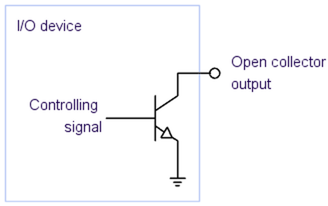
Figure 2. An I/O device with an open collector output.
In principle an open collector output is very useful, for example the circuits shown in figure 3 could be used to switch the LED on and off (figure 3a); to make the TTL input read a logic 1 or logic 0 (figure 3b); or activate the relay (figure 3c).
However, the problem with open-collector outputs from a input/output interfacing point of view is that they usually only work at relatively low voltages and currents - around 12VDC and 100 milliamps maximum.
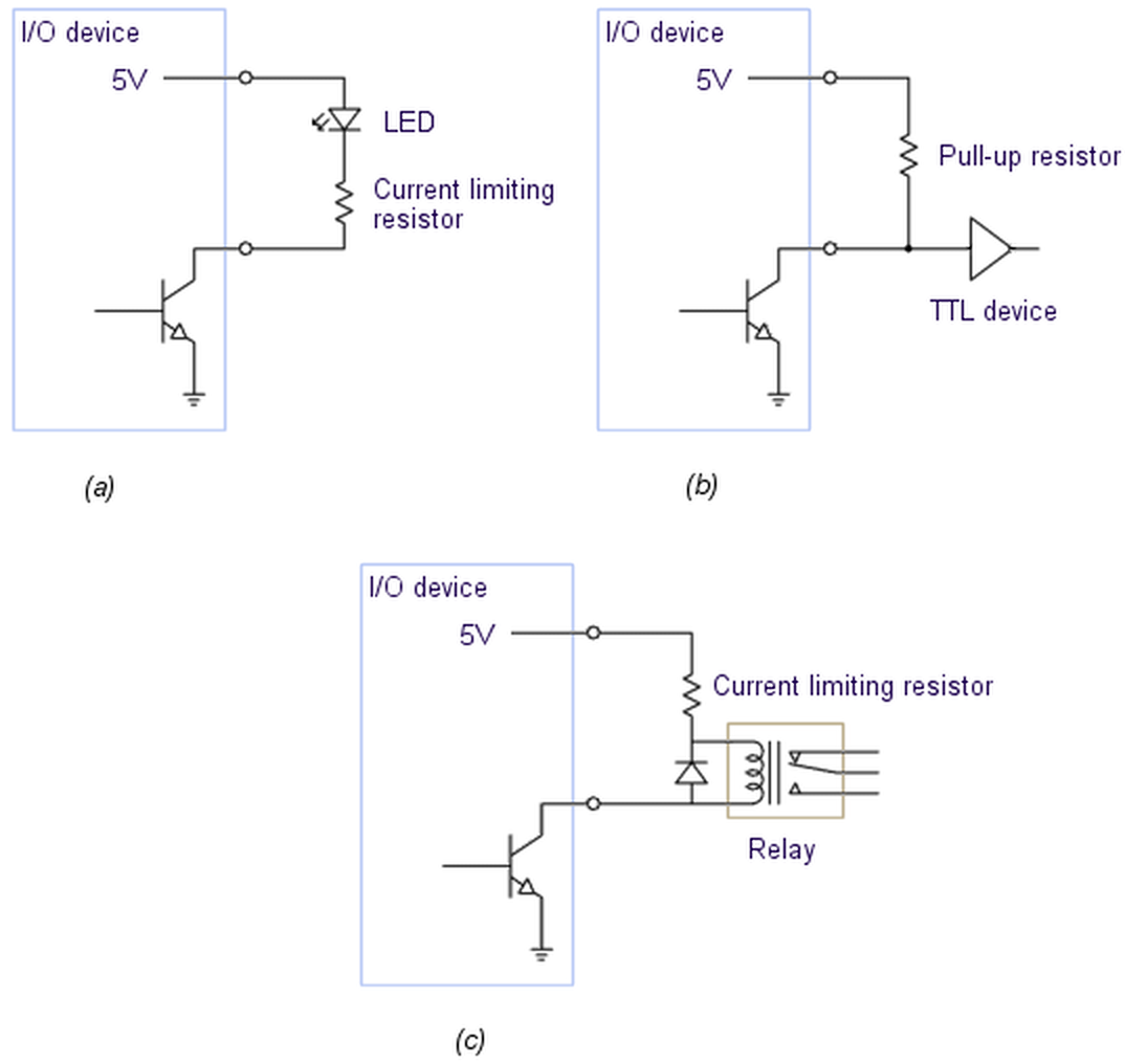
Figure 3. (a) An open collector output used to control an LED; (b) An open collector output used to provide an input to a TTL level input; (c) An open collector output used to control a relay.
So, to actually make use of an open collector output you will usually want to connect it to a relay (either mechanical or solid state) and have the relay switch the device you wish to control. The circuit in figure 3c can be used to do this. Here the diode is included to protect against voltage transients as the relay switches on and off.
![]()
© Copyright 2003-2026 Stoelting Co. All rights reserved
ANY-maze help topic T0921