ANY-maze Help > The ANY-maze reference > The I/O page > Making I/O connections > Connecting LEDs
Connecting LEDs

Details
To switch an LED on and off, you could use a similar circuit to the one used to control a light, (although you would need to include a current-limiting resistor), but provided the LED does not need more than 30mA current (and most don't), then you could connect it directly to a The ANY-maze Digital interface TTL output port (which would remove the need for an external power source).
Unlike incandescent bulbs, which can be connected directly to a power source (such as battery), LEDs need to include a current-limiting resistor, which, as the name implies, ensures that the current flowing through the LED is limited to an amount the LED can handle. This current limit is called the 'Forward current' (not to be confused with the 'Peak forward current') and will be reported in the LED's datasheet. Another value that the datasheet will report is the 'Forward voltage' and armed with these two values you can use ohm's law to calculate the required current-limiting resistor:
Resistor = (Power source voltage - LED Forward voltage) / Forward current
When connecting to an ANY-maze Digital interface TTL output port, the power source voltage is 5V and the Forward current should be the smaller of the LED's forward current and 30mA (which is the maximum the port can provide). So, typical values might be R = (5 - 1.8) / 0.025 = 128, so you'd need a 128 ohm resistor. Resistors are very cheap and can be found on-line or at shops like RadioShack. If you can't get the exact value required just get one that has a slightly higher resistance, perhaps 130 ohms in our example.
You'll actually connect the LED to pins 1 and 2 (odd numbered ports) or pins 3 and 4 (even numbered ports) of an ANY-maze Digital interface port, taking care to connect it the right way round (if you connect it the wrong way round, you won't damage it, it just won't work).
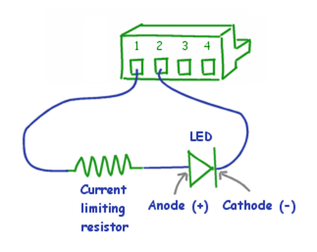
Figure 1. A circuit for connecting an LED to an ANY-maze Digital interface TTL output port.
After connecting the LED, you will need to configure the ANY-maze Digital interface so that it knows that the port you've connected to is being used to switch an LED on and off - specifically you'd set the port to be a TTL output. You should then test that the beam is working correctly using the I/O page, where you'd want to select the relevant ANY-maze interface's Output switch ports.
To actually use the LED in an experiment, you'll need to add it to the protocol as an on/off output. You'll probably also want to add a procedure, as it's the procedure which will actually turn the LED on and off during tests.
See also:
| • | The ANY-maze Digital interface |
| • | The ANY-maze Digital interface TTL output ports |
| • | Configuring the ANY-maze Digital interface |
| • | An introduction to on/off outputs |

© Copyright 2003-2026 Stoelting Co. All rights reserved
ANY-maze help topic T0905