ANY-maze Help > I/O devices supported by ANY-maze > Legacy I/O devices > The ANY-maze Parallel Rod interface (legacy)
The ANY-maze Parallel Rod interface (legacy)
![]()
| The Parallel Rod interface is a legacy system and has been replaced by the Parallel Rod cage, which interfaces to ANY-maze via the ANY-maze Touch switch interface. This help topic exists for users of the older (legacy) Parallel Rod interface. |
Introduction
The ANY-maze Parallel Rod interface is a USB device which is designed to detect 'foot slips' in the parallel rod test. The device is very simple: on one side it connects to a USB port on your computer, while on the other side it connects to the rods and floor of up to 4 parallel rod cages.
| • | Connecting the Parallel Rod interface to your computer |
| • | Testing the Parallel Rod Interface |
| • | Using the Parallel Rod Interface in an experiment |
Connecting the Parallel Rod interface
Installing the driver
| You must be running ANY-maze as an administrator in order to install drivers. To do this, right-click on the icon you use to start ANY-maze and then select 'Run as administrator' from the menu which appears. (If you run ANY-maze by clicking on an icon in the Windows task bar at the bottom of the screen, then you should right-click the icon, then right-click the entry that reads 'ANY-maze' and then select 'Run as administrator' from the menu which appears). |
IMPORTANT: You should install the driver software BEFORE you connect the Parallel Rod interface to your computer.
The driver software is a standard component of the ANY-maze system, and can be installed from within ANY-maze itself by following these steps:
| 1. | Close any open experiment. |
| 2. | Switch to the Support page. |
| 3. | In the list on the left side of the page, select Drivers. |
| 4. | The right-hand side of the page will display the ANY-maze driver settings (see figure 1 below) and towards the top of the list you will see an entry for ANY-maze USB devices which will report the current installed-state of the driver. |
| 5. | If the driver is not installed, first select it in the list and then click the |
For further details, see the ANY-maze USB device driver topic.
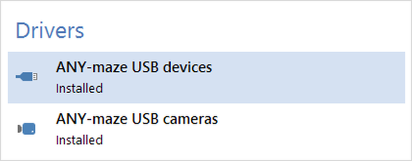
Figure 1. To install the AMi driver, you should select the ANY-maze USB driver entry and then click 'Install' in the ribbon bar.
Connecting the interface
Once the driver is installed, you can connect the interface to your computer. It simply plugs into any USB port, including ports on USB hubs. The cable is powered directly from the USB port and draws a current of just 100mA, so it should work correctly even with an unpowered hub.
Connecting the interface to a cage is also straightforward. Just plug the black connector into the base plate and the red connector into the grid floor. As a final test, you can use anything conductive to simulate a paw slip by using it to touch both a rod and the base at the same time - the cage's input should then be shown as 'on'.
Testing the Parallel Rod Interface
Before you start using the interface in an experiment, it's a good idea to test that it is working correctly. Here's what you need to do:
| • | Start ANY-maze. |
| • | Switch to the I/O page - there you should see the interface listed on the left side of the page. |
| • | Click the interface in the list and it will open to show a list of ports - in fact it will just have a single entry for Input switches, select it. |
| • | The right-hand side of the I/O the page will then show a graphical representation of the interface's four inputs - see figure 2. |
| • | Plug a cable into the connector labelled 'Cage 1' and then touch together the two connectors on the other end of the cable - the switch should be shown 'on', i.e. in green. |
| • | In fact, the switch is a 'touch' switch, which means that if you touch both the connectors (without them touching each other), then the switch should still be shown as 'on'. |
You should unplug the cable from the 'Cage 1' connector and plug it into 'Cage 2', and test that channel too - then test cages 3 and 4 as well.
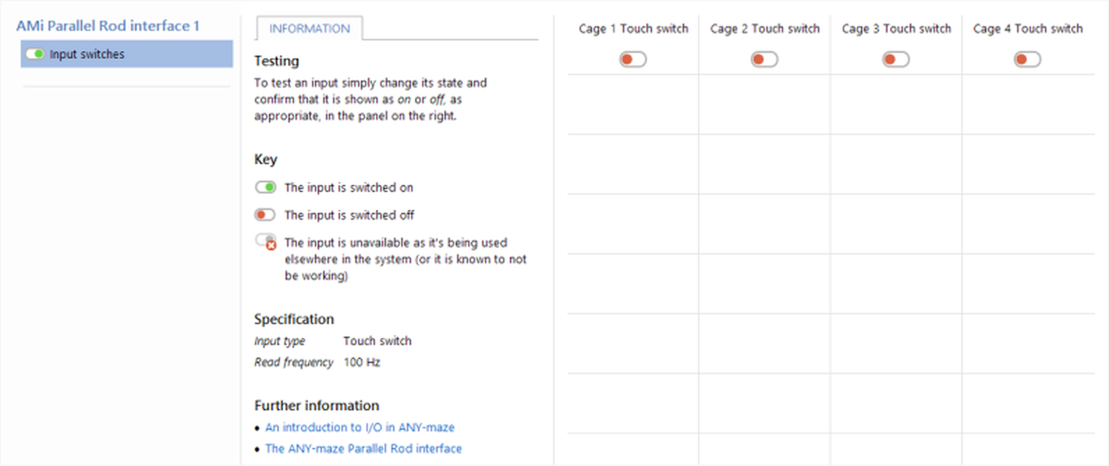
Figure 2. Testing the inputs of the Parallel Rod Interface. All cages are currently off.
See also:
| • | An introduction to on/off inputs |
| • | Setting up an on/off input |
![]()
© Copyright 2003-2026 Stoelting Co. All rights reserved
ANY-maze help topic T1299