ANY-maze Help > I/O devices supported by ANY-maze > Legacy I/O devices > The ANY-maze interface (AMi) > Installing and configuring AMi > Configuring AMi > AMi configuration - General Purpose I/O
AMi configuration - General Purpose I/O
![]()
| To access the AMi configuration window, select your AMi device in the list on the left side of the I/O page and then click the button to Configure this device in the ribbon bar. |
Introduction
As the name implies, the AMi general purpose I/O ports can be used in a number of different ways; for example as simple switch inputs, as photobeam inputs, as TTL level outputs, etc.
The General purpose I/O page of the AMi configuration window is used to specify how each port should be used.
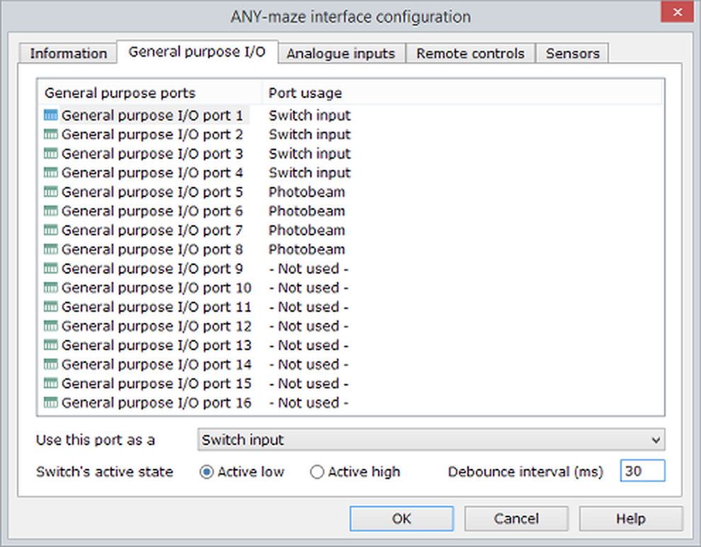
Figure 1. The General Purpose I/O page of the AMi configuration window.
Details
To set a port's configuration, you should simply select it in the ports list and then use the drop-down list at the bottom of the page to specify how it will be used.
If you hold down the Ctrl key when you click, you can select multiple ports and set the configuration for all of them simultaneously.
There are nine possible configurations for a GPIO port:
| • | Switch input |
| • | Photobeam |
| • | Photobeam arrays |
| • | Touch switch |
| • | Rotary encoder |
| • | Rotary encoder (doubled pulses) |
| • | Rotary encoder (two ports) |
| • | Switch output |
| • | Not used |
Switch input
Configuring a GPIO port as a switch input allows the port to detect simple on/off switch closures. This configuration can also be used for TTL or CMOS level inputs.
When a port is set to be a switch input, options will be displayed at the very bottom of the GPIO configuration page for you to choose the input's activate state and debounce interval (see figure 1, above).
The active state defaults to Active low as this is appropriate for a simple on/off switch - the input being high when the switch is open and low when the switch is closed.
The debounce interval is used to eliminate the effects of contact bounce, which could otherwise cause erroneous counts of contact closures. For most mechanical switches, you can either leave this field blank (in which case ANY-maze will use a default interval) or you can enter a small value, for example 30ms. However, in some case you may need to enter a much larger interval - for example, imagine you have connected a sensor to a swing door that the animal can open. When the door closes it will probably bounce open and closed a few times and this could last for as much as half a second, so in this case you would need to enter a debounce interval of 500ms so only one door opening would be scored.
To learn more about actually connecting input switches or TTL level inputs, refer to:
| • | Connecting on/off switches to the GPIO ports |
| • | Using the GPIO ports as TTL level inputs |
Photobeam
Configuring a GPIO port as a photobeam allows the port to be connected directly to a photobeam emitter (an infra-red LED) and a photobeam detector (an infra-red transistor) to detect beam breaks.
In the case of a photobeam, there are no further configuration options.
To learn more about connecting photobeams, refer to Connecting photobeams to the GPIO ports.
Photobeam arrays
Configuring a GPIO port as a photobeam array allows the port to be connected directly to an AMi photobeam array.
The photobeam arrays are available in different lengths and you should select the option which matches the length of the array you will be using. Note that arrays wider than 20cm 'use' multiple ports; this doesn't mean that you need to connect them to multiple ports, but rather that when such an array is connected to a GPIO port some other ports will automatically be disabled. Specifically, a 40cm photobeam array uses two GPIO ports and a 100cm array uses five. Thus, if you connect a 40cm array to GPIO port 1, port 2 will automatically be disabled, making it unavailable for other devices. This multi-port usage is automatically managed by the GPIO port configuration so you don't have to do anything about it other than make sure you connect the array to the correct port - in the case of the 40cm array, this means connecting to port 1, 3, 5 etc. and for the 100cm array, connecting to ports 1, 6 or 11. Note that the 20cm photobeam arrays don't use multiple ports, so you can connect up to 16 of them; one to each of AMi's GPIO ports.
There are no other configuration options for photobeam arrays available with the GPIO configuration settings, but the arrays can have their individual beams enabled and disabled in the I/O page.
To learn more about connecting photobeam arrays, refer to Connecting photobeam arrays to the GPIO ports.
Touch switch
A touch switch detects when the two terminals of the switch are touched by an animal. For example, you could connect one terminal to a water bottle spout and the other terminal to a grid floor and then the switch would register as on when the animal licks the spout. To actually use a GPIO port as a touch switch requires the 'AMi GPIO port Touch switch adaptor', which is available as an add-on for your AMi system.
In the case of a touch switch, there are no further configuration options.
To learn more about connecting touch switches, refer to Connecting touch switches to the GPIO ports.
Rotary encoders
A rotary encoder is a device that detects turns of an axle. There are a wide range of encoders available on the market, and we've even met some labs who have built their own.
A rotary encoder has two output lines which need to be connected to AMi, but a GPIO Port only has a single input. To address this, you have two options:
| • | You can use the 'GPIO port rotary encoder adaptor' add-on, which connects an encoder to a single GPIO port. In this case, you should simply configure the port as a Rotary encoder. |
| • | Alternatively, you can use two ports for the encoder, which avoids the need for any additional equipment. In this case, you should configure the port as a Rotary encoder (two ports). |
| • | There is also a third configuration option of Rotary encoder (doubled pulses). This is a variant of the simple Rotary encoder option (so it requires the use of the 'GPIO port rotary encoder adaptor' add-on), but it reports twice as many pulses for a rotation of the encoder. |
As a rotary encoder turns it outputs pulses. The number of pulses per rotation (PPR) is a defining characteristic of an encoder, and will be given in its technical specification. Clearly, for ANY-maze to know when an encoder completes a rotation, it needs to know this PPR value. Therefore, when a port is configured for any of the rotary encoder types, options will be displayed at the very bottom of the GPIO configuration page for you to specify the number of pulses per rotation. There's also an option to invert the encoder's direction, as ANY-maze may see the encoder rotating clockwise when it's actually turning anti-clockwise, and vice versa - checking the box corrects this.
To learn more about connecting rotary encoders, refer to Connecting rotary encoders to the GPIO ports.
Switch output
Configuring a port as a switch output will cause ANY-maze to output a TTL level 1 when the port is active and a TTL 0 when inactive. This can be useful if you have a device with a TTL level input, but you can also use the 'AMi GPIO port relay adaptor' add-on to convert this into a relay output capable of switching up to 40 volts (AC or DC) at 1.5A, which makes the output more widely applicable.
In the case of a switch output, there are no further configuration options.
To learn more about using GPIO ports as outputs, refer to:
| • | Using the GPIO ports as a TTL level output |
| • | Connecting a solid state relay to the GPIO ports |
Not used
When a port is configured as Not used, AMi will make it into an input and then ignore it. This means AMi won't read the port, which reduces the amount of information AMi sends to ANY-maze and thus the amount of processing ANY-maze needs to perform.
![]()
© Copyright 2003-2026 Stoelting Co. All rights reserved
ANY-maze help topic T1156